13mm: Building a Stereo SLAM System from Hardware That Wasn't Designed for It
- used my iPhone as a stereo camera
- streamed frames to my Mac over USB and ran SLAM on them in real time
- built a dense 3D reconstruction of whatever I pointed it at
- custom OpenGL renderer for output
The Premise
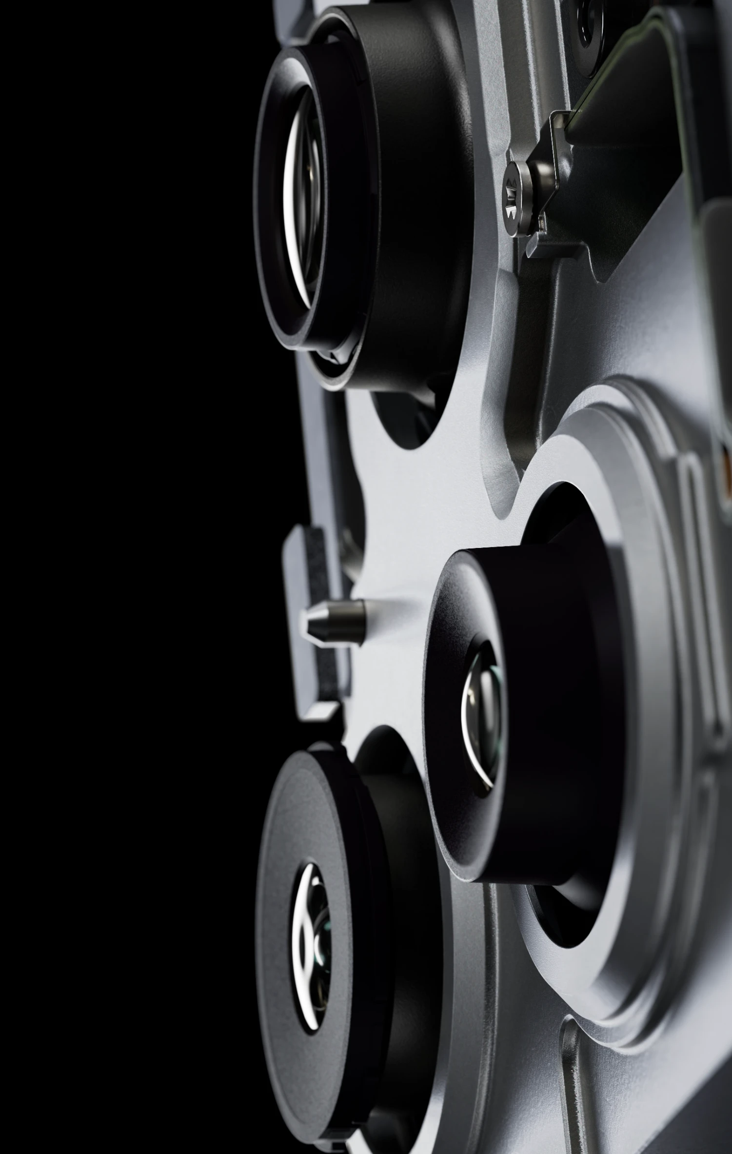
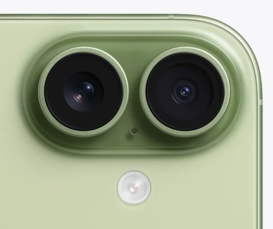
The iPhone has two rear cameras. Can I treat them as a stereo pair and build a dense 3D map of a room in real time?
The short answer is yes, with significant caveats. The cameras were designed for computational photography, not stereo vision. They have different focal lengths, iOS exposes no stereo calibration API, and the baseline—the physical distance between camera centers—is roughly 13mm. Professional stereo rigs in robotics typically run 10–30cm. My baseline is about the width of a thumb.
A narrow baseline directly limits depth precision: the farther an object is, the smaller its disparity, and the worse a pixel-level error in disparity translates to meters of depth error.
Capturing Stereo Data on iPhone
I built a Swift app for sensor capture, it has three jobs: get sync'd frames from both cameras, collect IMU data, and stream everything to the Mac.
Synchronized capture. iOS provides AVCaptureMultiCamSessionAVCaptureDataOutputSynchronizer
FOV matching. The wide and ultrawide cameras have different focal lengths—roughly 26mm and 13mm equivalent. A stereo pair needs both cameras looking at the same scene at the same scale, so I digitally zoom the ultrawide to match the wide camera's field of view. This is a crop, not an optical zoom: the ultrawide captures at full resolution and the center region is extracted, meaning I do lose data. However, the useful side effect is that I'm operating in the low-distortion center of the ultrawide lens rather than its barrel-distorted periphery.
Calibration. iOS doesn't expose stereo calibration parameters directly, so I calibrated offline using a checkerboard pattern. This gives accurate focal lengths, principal point, distortion coefficients, and the camera-to-camera rotation and translation.
Streaming protocol. Frames and IMU data are streamed over TCP to the Mac via a wired USB connection using usbmuxd, with a custom binary protocol. Each packet has an 8-byte header encoding packet type and payload length, followed by the payload:
[type: u32][length: u32][payload: bytes]

Type 0 - IMU (56 bytes):
  [8] timestamp (f64)
  [8] accel.x, accel.y, accel.z (f64 each)
  [8] gyro.x, gyro.y, gyro.z (f64 each)

Type 1 - Frame (17 + JPEG):
  [8] timestamp (f64)
  [1] camera_type (0=wide, 1=ultra)
  [4] width (u32)
  [4] height (u32)
  [...] JPEG payload

Type 2 - Calibration (sent once at session start):
  intrinsics and extrinsics for both cameras
Frames are JPEG-compressed at 80% quality before transmission. Raw frames at 640×480 are about 900KB each—at 30fps from two cameras that's ~54MB/s uncompressed. JPEG at 80% brings this down to roughly 2–3MB/s, well within USB bandwidth. Compression artifacts are minimal at 80% and become negligible after downscaling to 320×240 for stereo matching.
TCP vs. UDP: the length-prefixed framing requires ordered delivery—out-of-order packets would break the parser. TCP provides this guarantee for us cheaply, removing the need to implement sequence numbers and reordering in application code. Over USB, packet loss is essentially zero so there's no practical case where UDP's "skip and move on" behaviour would be preferable.
IMU data is sent at 100Hz via CMMotionManager
Stereo Rectification
Before stereo matching, the images need to be rectified. In an ideal stereo setup the two cameras are perfectly parallel and share the same image plane—corresponding points lie on the same horizontal row. No physical setup achieves this; factory-calibrated stereo cameras have the same problem, which is why they ship with calibration data burned in. Rectification is how every stereo system closes the gap between imperfect hardware and ideal geometry.
Rectification warps both images so that they satisfy this constraint. Geometrically, the epipolar linesare rotated to become horizontal scanlines. After rectification, finding a correspondence between a pixel in the left image and its match in the right image is a 1D search along a row rather than a 2D search across the entire image. This is what makes dense stereo matching computationally tractable.
OpenCV's stereoRectify
cv::stereoRectify(
    calib.K_wide, calib.dist_wide,     // left camera intrinsics + distortion
    calib.K_ultra, calib.dist_ultra,   // right camera intrinsics + distortion
    calib.image_size,
    calib.R, calib.T,                  // rotation and translation between cameras
    R1, R2,                            // output: rectification rotations
    P1_, P2_,                          // output: new projection matrices
    Q_,                                // output: disparity-to-depth matrix
    cv::CALIB_ZERO_DISPARITY,
    -1                                 // alpha = -1: auto-scale to avoid black borders
);
The outputs are two sets of remapping tables (map1, map2 for each camera) that encode the per-pixel warping. Applying them via cv::remap produces the rectified images:
cv::remap(left_raw,  left_rect,  map1_left_,  map2_left_,  cv::INTER_LINEAR);
cv::remap(right_raw, right_rect, map1_right_, map2_right_, cv::INTER_LINEAR);
The projection matrices P1 and P2 also encode the effective baseline after rectification. The baseline is recovered from P2's first row:
baseline_ = -P2_.at<double>(0, 3) / P1_.at<double>(0, 0); // ~0.013m
The QstereoRectify encodes the full disparity-to-3D mapping. For a pixel at (u, v) with disparity d:
[X, Y, Z, W] = Q · [u, v, d, 1]^T
depth = Z / W
This is used downstream in depth conversion.
Pose Tracking with ORB-SLAM3
Rectified stereo pairs and IMU measurements are passed into ORB-SLAM3, running in IMU_STEREO
Feature extraction and matching. ORB-SLAM3 extracts ORB features from each frame—oriented, scale-invariant FAST corners with a binary descriptor. The stereo configuration lets features be triangulated directly: for a feature at pixel (u, v) in the left image with a match at (u - d, v) in the right image, the depth is:
Z = (baseline × fx) / d
IMU preintegration. Between consecutive frames, the IMU delivers hundreds of measurements. Rather than incorporating each one individually into the optimization, ORB-SLAM3 uses IMU preintegration: all measurements between two keyframes are compressed into a single relative motion constraint. The preintegrated measurement encodes relative rotation, velocity, and position change, along with precomputed Jacobians with respect to the IMU biases. If the bias estimates change during optimization—which they do as the system refines them—the preintegrated constraint can be cheaply corrected via these Jacobians rather than reintegrating from scratch.
The full visual-inertial state vector estimated at each keyframe includes camera pose, velocity, accelerometer bias, and gyroscope bias. Pure stereo SLAM doesn't estimate velocity or biases. The IMU also gives a gravity reference that constrains roll and pitch, which helps with scale consistency over time.
Keyframe insertion. Not every frame becomes a keyframe. ORB-SLAM3 monitors the fraction of tracked map points well-observed by the current reference keyframe. When this drops below a threshold—meaning enough of the scene is genuinely new or tracking has degraded—a new keyframe is inserted. There are additional constraints on minimum temporal separation to prevent keyframe flooding in feature-rich regions. The resulting keyframe set is sparse but well-conditioned for local bundle adjustment.
My modifications. I disabled the built-in Pangolin viewer and replaced it with a custom GLFW
slam.setKeyframeCallback([&](const KeyframeData& kf_data) {
    // Capture current rectified frames
    cv::Mat left_rect, right_rect, left_rgb;
    {
        std::lock_guard<std::mutex> lock(frames_mutex);
        left_rect = last_left_rect.clone();
        right_rect = last_right_rect.clone();
        left_rgb   = last_left_rgb.clone();
    }

    // Push fusion task to queue
    KeyframeTask task;
    task.pose      = kf_data.pose;
    task.K         = kf_data.K.clone();
    task.left_rect = left_rect;
    task.right_rect = right_rect;
    task.left_color = left_rgb;

    std::lock_guard<std::mutex> lock(queue_mutex);
    task_queue.push(task);
    queue_cv.notify_one();
});
There's a subtle timing issue worth acknowledging: the keyframe callback fires from inside ORB-SLAM3 after it has decided to create a keyframe, but last_left_rect is continuously overwritten by the main loop at ~25fps. If the main loop has advanced a frame or two before the callback fires and takes the lock, the frames captured in the callback may not be identical to the ones ORB-SLAM3 used to create the keyframe. At 25fps the worst-case offset is ~40ms. In practice at slow indoor movement the frames are nearly identical, and the .clone() ensures the fusion thread sees a consistent snapshot. It's a correctness trade-off that works for this use case.
The proper fix is a timestamped frame buffer—a small circular buffer of recent rectified frames keyed by timestamp, so when the callback fires you look up the frame that matches the keyframe's timestamp rather than grabbing whatever happens to be current.
Dense Depth from Stereo Matching
ORB-SLAM3 produces a sparse map, typically a few thousand 3D feature points per keyframe. This is sufficient for tracking but not for surface reconstruction.
Semi-Global Block Matching. I use OpenCV's StereoSGBM
Naive block matching finds the best match for each pixel independently, which tends to produce noisy results—especially in low-texture regions where patches look similar across a range of disparities. SGBM improves this by incorporating spatial smoothness. Matching costs are aggregated along multiple 1D paths across the image (typically 8 directions) with penalties added for disparity changes between adjacent pixels. P1P2
matcher_ = cv::StereoSGBM::create(
    0,     // minDisparity
    96,    // numDisparities—search range, must be divisible by 16
    5,     // blockSize—5x5 SAD window
    8 * 5 * 5,   // P1 = 200—penalty for disparity change of 1
    32 * 5 * 5,  // P2 = 800—penalty for larger disparity change
    1,     // disp12MaxDiff
    63,    // preFilterCap
    10,    // uniquenessRatio
    100,   // speckleWindowSize
    32,    // speckleRange
    cv::StereoSGBM::MODE_SGBM
);
SGBM is "semi-global" because it approximates a full 2D global optimization by solving along 1D scanlines independently and summing the path costs. Each 1D path is solvable in linear time via dynamic programming. Combining multiple directions gives most of the spatial coherence of a global method at a fraction of the cost.
The output is a 16-bit fixed-point disparity map where the true disparity in pixels is disparity_value / 16.0. Depth is then:
float disp_pixels = disparity.at<int16_t>(y, x) / 16.0f;
float depth_meters = (baseline_ * fx_) / disp_pixels;
The baseline problem. At z = 2m with a 13mm baseline and fx ≈ 920px:
d = (0.013 × 920) / 2.0 ≈ 6 pixels
A 1-pixel disparity error gives depth (0.013 × 920) / 5 ≈ 2.4m—a ~0.4m error. At 0.5m the same calculation gives 24 pixels of disparity and roughly 2cm of depth error per pixel. Depth precision degrades quadratically with distance, which is why the system is constrained to close-range use.
numDisparities = 96
Performance. At 640×480, SGBM takes ~300ms—far too slow for real-time use. Downscaling to 320×240 reduces this to ~80ms:
cv::resize(task.left_rect,  left_small,  cv::Size(320, 240));
cv::resize(task.right_rect, right_small, cv::Size(320, 240));
cv::Mat depth_small = stereo_matcher.computeDepth(left_small, right_small);
cv::resize(depth_small, depth_full, task.left_rect.size());
The depth map is upscaled back to full resolution before TSDF integration. The camera matrix K is adjusted to account for the scale change:
cv::Mat K_scaled = task.K.clone();
K_scaled.at<double>(0,0) *= (double)task.left_rect.cols / 320.0;  // fx
K_scaled.at<double>(1,1) *= (double)task.left_rect.rows / 240.0;  // fy
K_scaled.at<double>(0,2) *= (double)task.left_rect.cols / 320.0;  // cx
K_scaled.at<double>(1,2) *= (double)task.left_rect.rows / 240.0;  // cy
Valid depth coverage in practice is 40–60% of pixels in textured regions. Featureless surfaces produce no valid disparity because there's nothing to match. These become holes in the depth map. TSDF averaging partially fills them over multiple views as the camera moves, but structured holes persist in large untextured areas.
TSDF Fusion
Dense depth maps from a moving camera need to be fused into a consistent 3D representation. I implemented a TSDF volume from scratch rather than using an existing library like Voxblox. Did this so I could better understand the algorithm, even if I had to fall back to Voxblox at a later date.
Data structure. The volume is a dense 3D grid of voxels. At 100³ voxels with 5cm resolution, the grid covers a 125m³ space and sits at around 11MB. A production system would use sparse voxel hashing to only allocate voxels near observed surfaces, which would scale to much larger environments without the fixed memory ceiling.
struct TsdfVoxel {
    float distance;   // signed distance to nearest surface (meters)
    float weight;     // accumulated observation weight, capped at 100
    uint8_t r, g, b;  // fused RGB color
};
Coordinate mapping. The volume is centered at the world origin. Converting between world position and voxel index:
Eigen::Vector3i TsdfVolume::worldToVoxel(const Eigen::Vector3f& world_pos) const {
    Eigen::Vector3f grid_pos = (world_pos - origin_) / voxel_size_;
    return Eigen::Vector3i(
        static_cast<int>(std::floor(grid_pos.x())),
        static_cast<int>(std::floor(grid_pos.y())),
        static_cast<int>(std::floor(grid_pos.z()))
    );
}
Voxels are stored in a 1D array with row-major indexing: index = x + y · grid_size + z · grid_size².
The SDF. For a voxel at world position p, the signed distance value is:
sdf(p) = ray_length - dist_from_camera_to_p
Positive values mean the voxel is in front of the measured surface (between the camera and the surface). Negative values mean it's behind. Zero is the surface itself. The truncation clamps this to [-truncation, +truncation], ignoring voxels far from any measured surface:
float sdf = ray_length - dist;
sdf = std::max(-truncation_distance_, std::min(truncation_distance_, sdf));
The truncation_distance_
Integration. For each pixel with valid depth, I backproject it to 3D, march along the ray, and update every voxel within the truncation band via weighted averaging:
// For each valid depth pixel (u, v) with depth z:
Eigen::Vector3f point_camera(
    (u - cx) * z / fx,
    (v - cy) * z / fy,
    z
);
Eigen::Vector3f point_world = T_world_camera * point_camera;
Eigen::Vector3f ray_dir = (point_world - camera_pos_world).normalized();
float ray_length = (point_world - camera_pos_world).norm();

float start_dist = std::max(0.0f, ray_length - truncation_distance_);
float end_dist   = ray_length + truncation_distance_;

for (float dist = start_dist; dist < end_dist; dist += voxel_size_) {
    Eigen::Vector3f voxel_pos = camera_pos_world + ray_dir * dist;
    Eigen::Vector3i voxel_idx = worldToVoxel(voxel_pos);

    float sdf = ray_length - dist;
    sdf = std::max(-truncation_distance_, std::min(truncation_distance_, sdf));

    TsdfVoxel& voxel = getVoxel(voxel_idx);
    float updated_weight = std::min(voxel.weight + 1.0f, 100.0f);
    voxel.distance = (voxel.distance * voxel.weight + sdf * 1.0f) / updated_weight;
    voxel.weight   = updated_weight;

    // Color averaged the same way (BGR -> RGB)
    voxel.r = (voxel.r * old_weight + color[2]) / updated_weight;
    voxel.g = (voxel.g * old_weight + color[1]) / updated_weight;
    voxel.b = (voxel.b * old_weight + color[0]) / updated_weight;
}
The weight cap at 100 prevents old observations from dominating the average indefinitely. Without it, early noisy estimates would lock in and resist correction from later measurements.
Surface extraction. A point cloud is extracted by iterating all voxels and collecting those within one voxel width of the zero crossing with sufficient accumulated weight:
if (voxel.weight > 1.0f && std::abs(voxel.distance) < voxel_size_) {
    points.push_back(voxelToWorld(voxel_idx));
    colors.push_back({voxel.r / 255.0f, voxel.g / 255.0f, voxel.b / 255.0f});
}
This is a simple surface threshold rather than marching cubes. Marching cubes would produce a proper mesh with normals and continuous surfaces, better for visualization and lighting. The point cloud is sufficient for now and was simpler to implement correctly.
Loop closure and TSDF consistency. When ORB-SLAM3 detects a loop closure—recognizing that the camera has returned to a previously visited location—it corrects accumulated drift in the pose graph via bundle adjustment. The keyframe poses shift to be globally consistent. There is a problem where geometry already fused is baked in at the old drifted poses. The TSDF volume doesn't receive the correction. In a room-scale indoor scan where drift is modest, this creates small misalignments at the boundaries of loop-closed regions.
The correct fix is submap-based fusion: each submap has its own local TSDF that can be rigidly transformed when the pose graph corrects. This remains a known architectural limitation.
Asynchronous Fusion Architecture
Dense stereo matching (~80ms) and TSDF integration (~50ms) together take about 130ms per keyframe. Running this synchronously would cap the SLAM tracking rate at ~7fps. The solution is a dedicated fusion thread with a producer-consumer task queue.
The main thread runs the SLAM tracking loop at ~25fps. When ORB-SLAM3 creates a keyframe, the callback pushes a KeyframeTask into a thread-safe queue and returns immediately. The fusion thread blocks on this queue and processes tasks as they arrive:
// Fusion thread body
while (fusion_running) {
    KeyframeTask task;
    {
        std::unique_lock<std::mutex> lock(queue_mutex);
        queue_cv.wait_for(lock, std::chrono::milliseconds(100),
            [&]{ return !task_queue.empty() || !fusion_running; });

        if (task_queue.empty()) continue;
        task = task_queue.front();
        task_queue.pop();
    }

    // Process: dense stereo -> TSDF integrate -> extract point cloud -> update renderer
    cv::Mat depth = stereo_matcher.computeDepth(left_small, right_small);
    tsdf.integrateDepth(depth_full, task.left_color, task.pose, K_scaled);
    tsdf.extractPointCloud(points, colors);
    cloud_renderer.updatePointCloud(points, colors);
}
The fusion thread runs roughly 3x slower than the rate at which keyframes arrive during active exploration. When the queue backs up, older keyframe tasks are dropped in favor of newer ones. Skipped frames rarely leave visible gaps; the geometry is dense enough that occasional misses don't matter.
Shared state between threads is protected by mutexes: frames_mutex guards the current rectified frames, queue_mutex guards the task queue, and TsdfVolume has an internal mutex protecting all voxel reads and writes. The renderer uses a separate mutex for point cloud buffer swaps.
Visualization
Two GLFW windows run concurrently. The 2D tracking window displays the current frame with ORB features overlaid, updated at the SLAM tracking rate. The 3D point cloud window renders the reconstruction as it grows.
The point cloud renderer uses a standard OpenGL 3.3 VAO/VBO
layout(location = 0) in vec3 position;
layout(location = 1) in vec3 color;
uniform mat4 MVP;
out vec3 fragColor;

void main() {
    gl_Position = MVP * vec4(position, 1.0);
    gl_PointSize = 2.0;
    fragColor = color;
}
The vertex shader reads both and passes color through to the fragment stage. MVP
What's Next
There are a few low-hanging improvements. The most impactful is submap-based TSDF fusion, right now loop closure corrections from ORB-SLAM3 don't propagate back into the volume, so drift gets baked in permanently. Replacing SGBM with a learned stereo model like RAFT-Stereo would also meaningfully improve depth coverage in low-texture regions where block matching falls apart. And swapping the dense 100³ grid for sparse voxel hashing would remove the fixed memory ceiling and make extraction faster by skipping empty space entirely.
If you read any part of this, thanks!
If you have any questions, please reach out, I would love to chat.